- Welcome to North Reading Engineering HiFi Forum.
Recent posts
#1
Vintage McIntosh Amplifier Repairs, Restorations and Modifications / Re: MC30 pair for restoration
Last post by nre_admin - Apr 25, 2024, 05:37 AMCompleted pair.
#2
Vintage McIntosh Amplifier Repairs, Restorations and Modifications / Re: MC30 pair for restoration
Last post by nre_admin - Apr 25, 2024, 05:36 AMReplace multi-section cap with CE Mfg 80-40-30-20 550VDC. The 30MF isn't used.
#3
Vintage McIntosh Amplifier Repairs, Restorations and Modifications / Re: MC30 pair for restoration
Last post by nre_admin - Apr 25, 2024, 05:30 AMRecapped, replaced power cord, fuse holder, u/s clean of terminal barrier block.
#4
Vintage McIntosh Amplifier Repairs, Restorations and Modifications / Re: MC30 pair for restoration
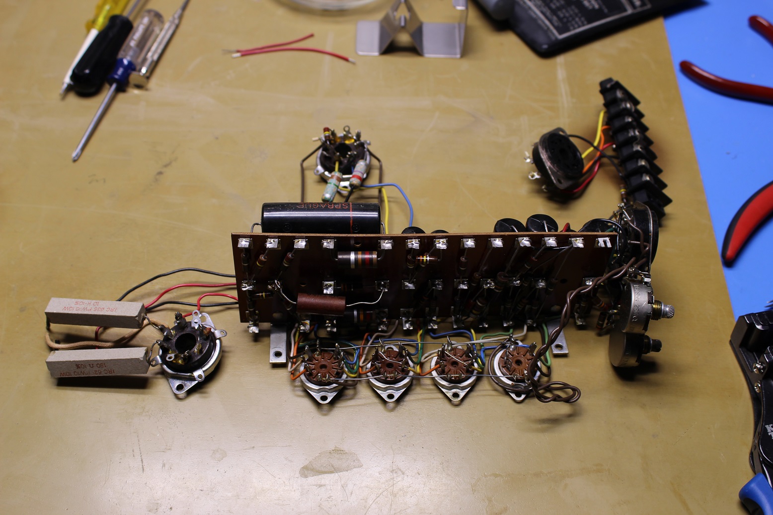
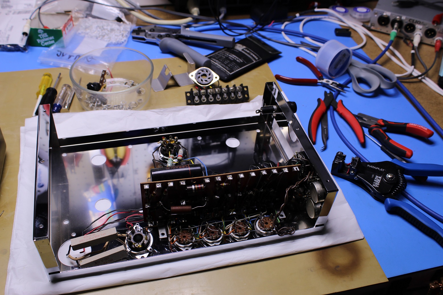
Last post by nre_admin - Apr 19, 2024, 05:28 AMRemoving the circuit as a whole assembly simplifies the rebuild process.
#5
Vintage McIntosh Amplifier Repairs, Restorations and Modifications / Re: MC30 pair for restoration
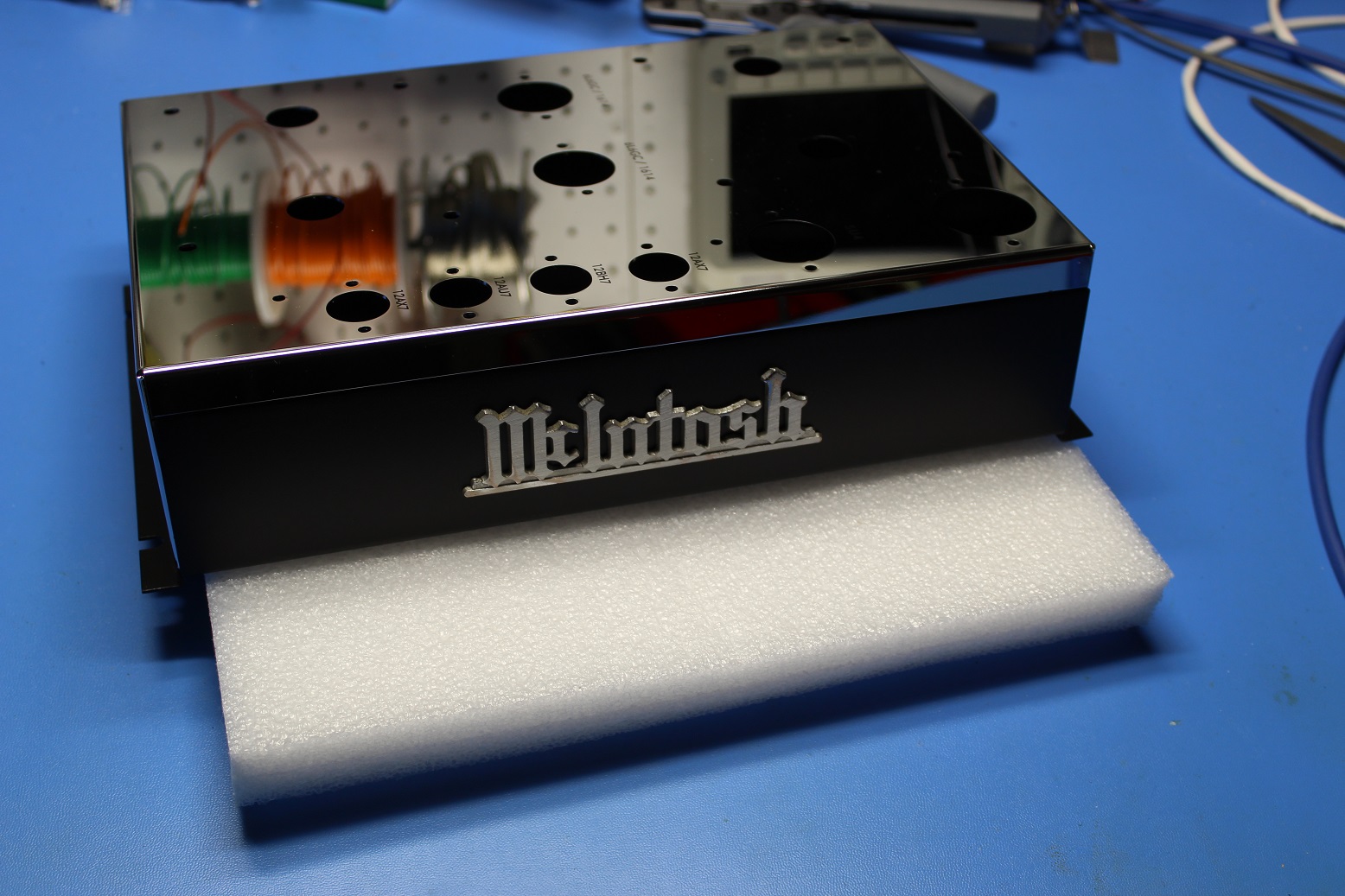
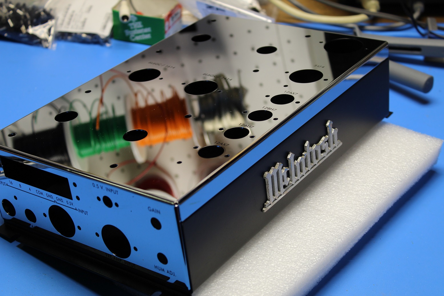
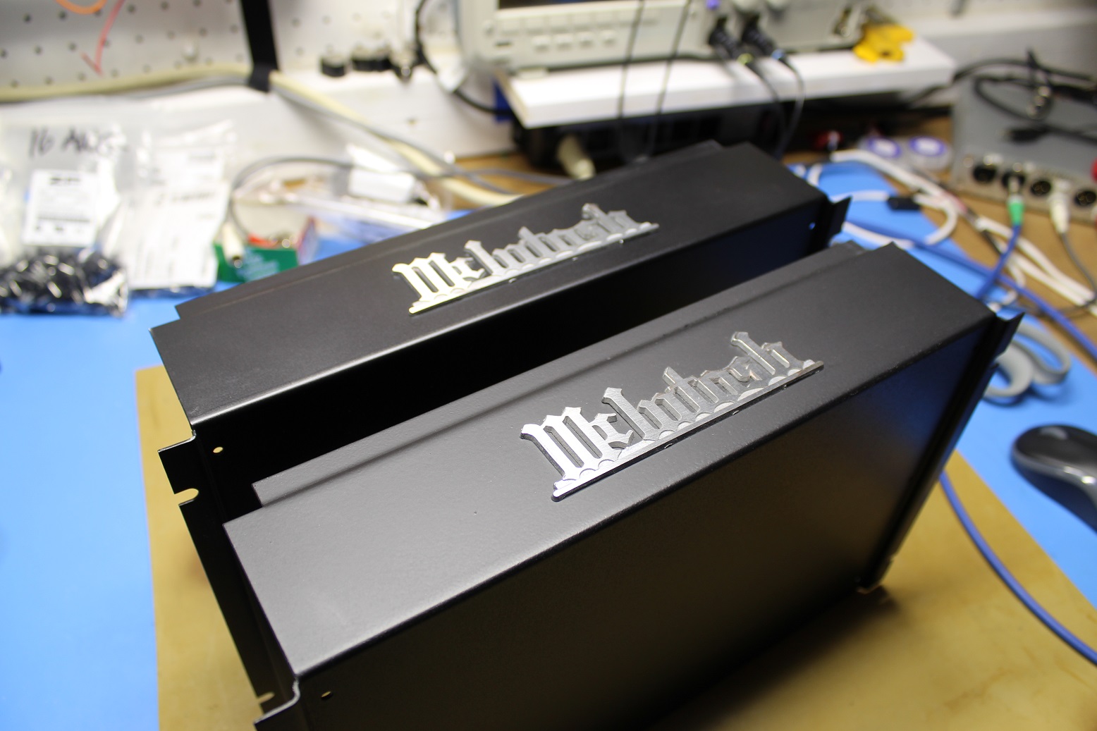
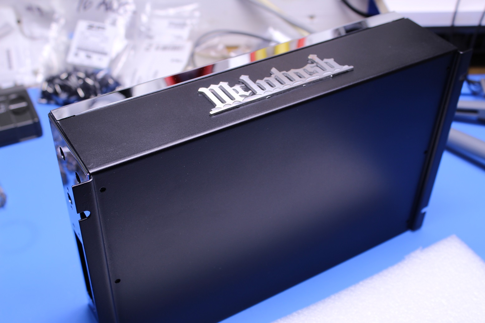
Last post by nre_admin - Apr 19, 2024, 05:26 AMNew, reproduction chassis tops from Korea. Not sure if they're fabricated in Korea. Quality is better than the original.
#6
Vintage McIntosh Amplifier Repairs, Restorations and Modifications / Re: MC30 pair for restoration
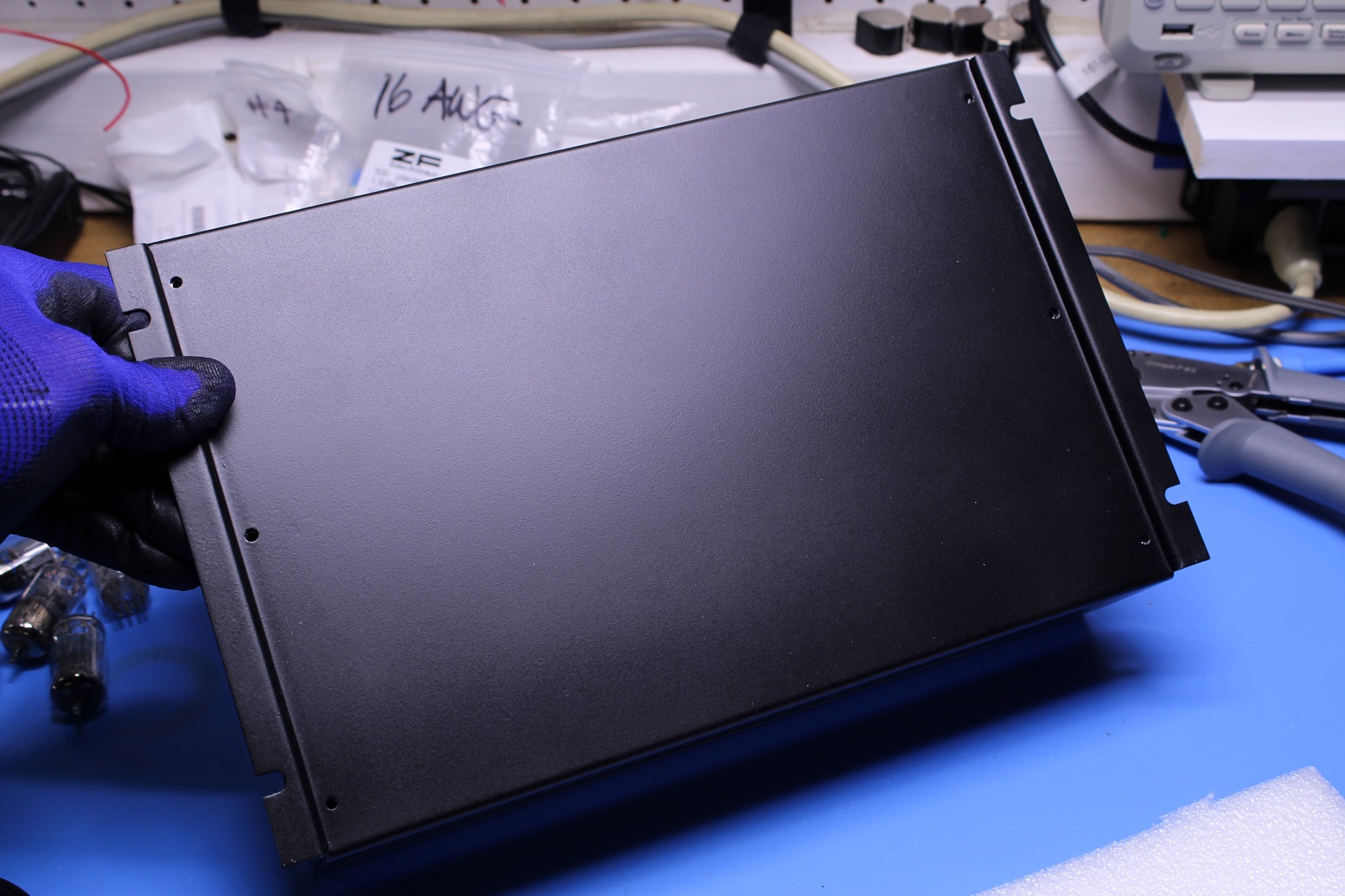
Last post by nre_admin - Apr 19, 2024, 05:22 AMSheet metal bottom chassis parts grit blasted, chemically etched, primed, painted then baked.
#7
Vintage McIntosh Amplifier Repairs, Restorations and Modifications / MC30 pair for restoration
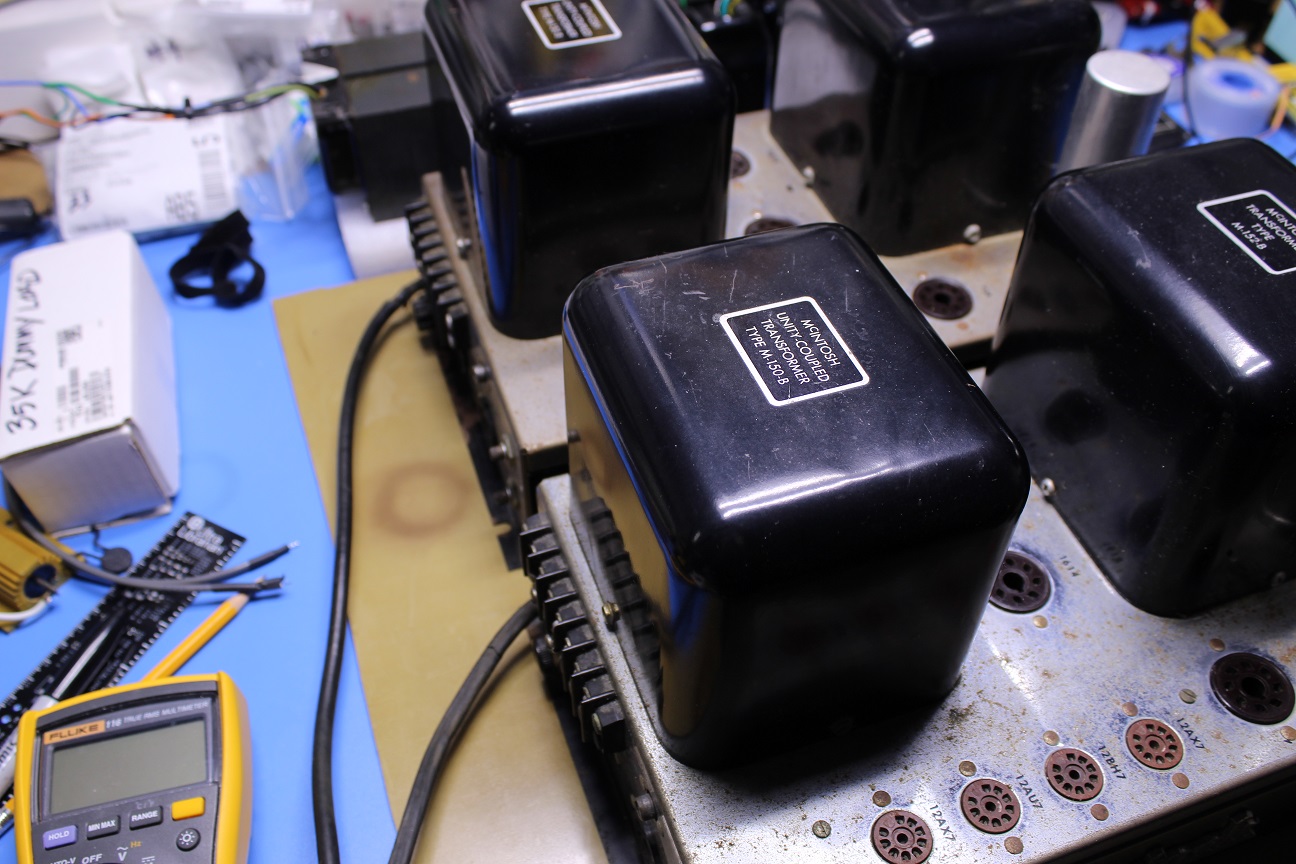
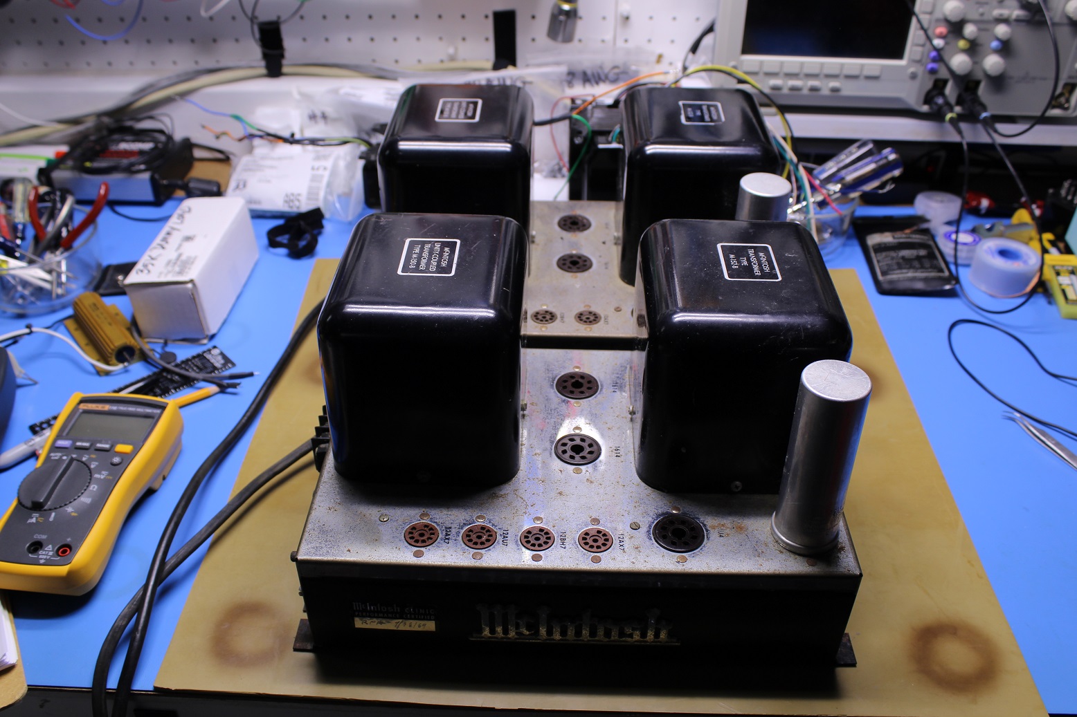
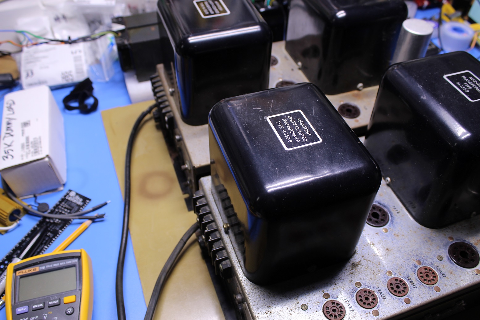
Last post by nre_admin - Apr 16, 2024, 06:59 AMDeep pitting and blister on both the top chassis cover chrome plating and bottom cover paint, heavy scale (corrosion) on the bottom covers too. There's a supplier in Singapore that makes a top cover replacement and the gent that owns these purchased a pair and provided them to me for this rework. The bottom covers are steel sheet and can be grit-blasted, chem-etched, primed, sprayed and then baked to a like new condition. The cast McIntosh emblem is a pot metal casting with a copper strike then chrome plated. These usually pit but bench out nicely on a stationary belt grinder and can be left in a benched condition.
Both power cords showed signs of rodent damage. Likely been sitting for some time out of sight. The internal components are original, nothing's been replaced.
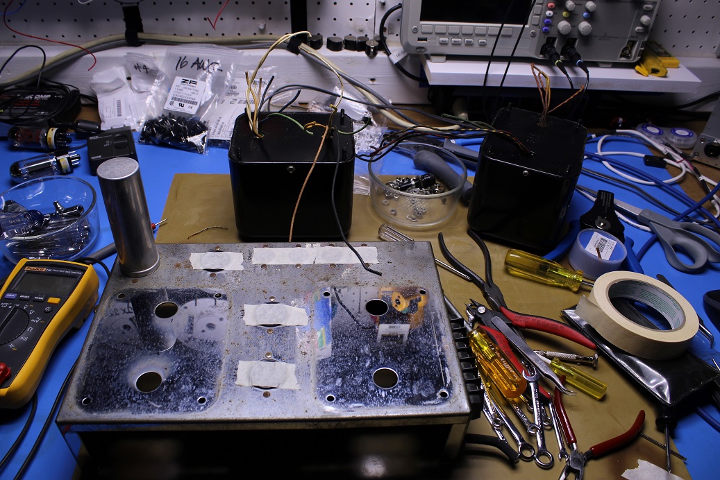
The workflow used on these:
1. remove power cord, Heyco strain relief, fuse holder
2. remove bottom cover, work separately.
3. remove transformers, check for troubles.
4. mask tube and octal sockets.
5. grind out rivet tops, all rivets.
6. remove as much of the internal circuitry as possible without breaking connections this includes the board and the sockets and pots attached to it.
7. remove barrier terminal, soak in cleaner, replace #6 fasteners with combination type
8. On the board replace germanium rectifier and dropping resistor with silicon, replace Bumblebee and Black Beauty caps with polypropylene types. The Bumblebee caps have high leakage current at rated voltage, must be replaced.
9. Replace single can electrolytic caps for bias supply, preamp
10. On replacement chassis top install new RCA input, barrier terminal and octal sockets, new fuse holder, new multi-section capacitor for power supply (CE Mfg).
11. Reinstall reworked board, pots and tube sockets
12. Install transformers
13. on Variac, spool amp up and measure all voltage magnitudes
#8
Vacuum Tube Amplifier Repairs, Restorations and Builds / Re: Scott 222C
Last post by duder1982 - Mar 13, 2024, 08:26 PMI love seeing these rebuilds. I too used the Sovtek EL84M in my 222c. Nicely done.
#9
Vintage McIntosh Amplifier Repairs, Restorations and Modifications / Re: Customer build and install
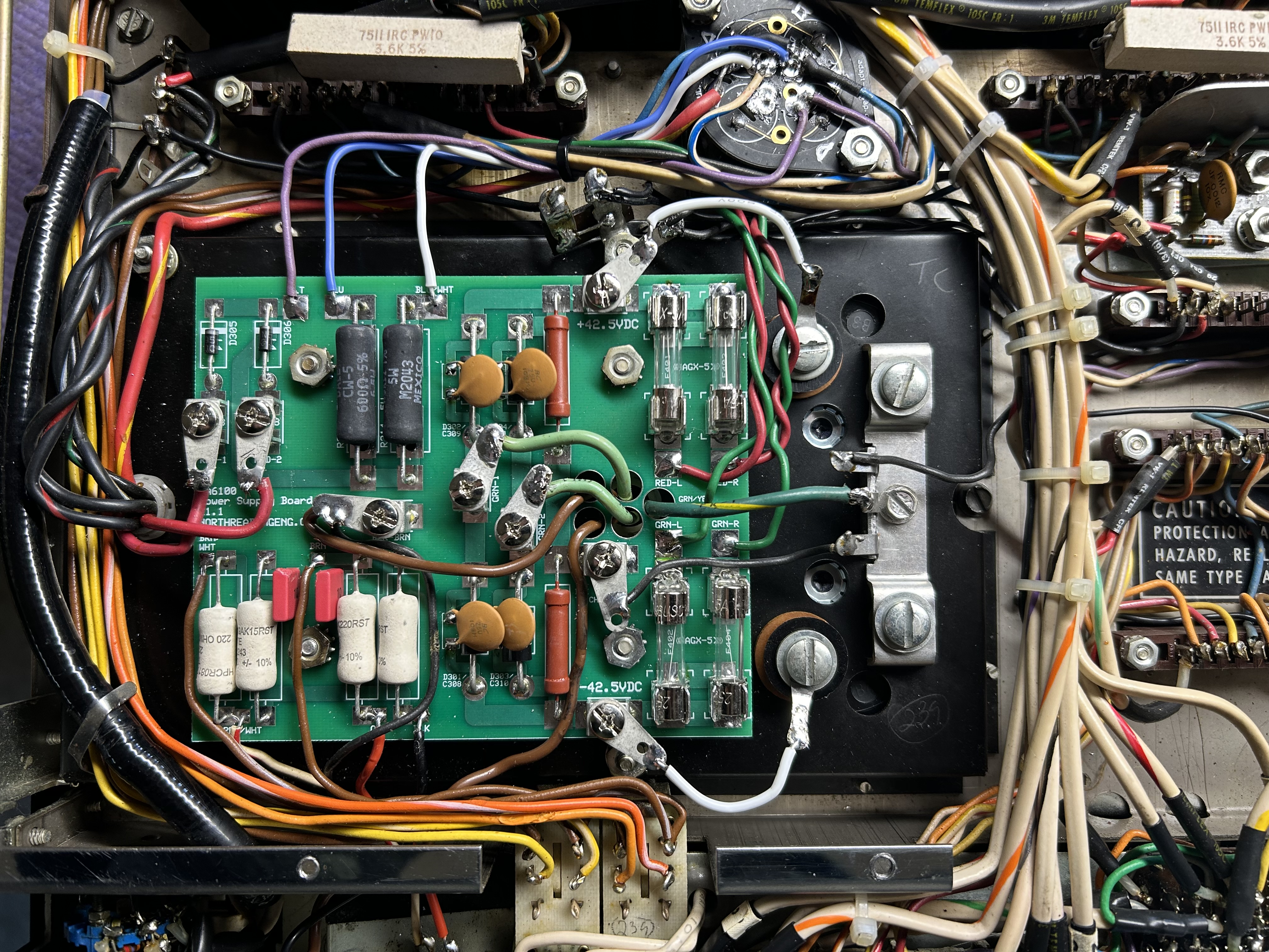
Last post by nre_admin - Mar 07, 2024, 07:13 AMCustomer install of MA6100 power supply board.
#10
Vacuum Tube Amplifier Repairs, Restorations and Builds / North Reading Model 219 Tube A...
Last post by nre_admin - Mar 01, 2024, 03:01 PMA few photos of a North Reading Engineering tube amp project completed recently. Two channels, about 20WRMS/ch into 8Ohms. Based somewhat on the Scott 299C output stage but using a solid-state, HV power supply design capable of substantially more power than is required for the push-pull 7591 pairs.
Chassis CAD files were sent out for quote, the supplier (New England based) responded with pricing for larger quantities than I was considering. Placed an order for a small lot of chassis assemblies. All metal chassis assemblies are best for RFI/EMI/noise immunity. The chassis assembly is the high-cost item in the build. Uses oversized Hammond or Lundahl output transformers.
Go to https://northreadingeng.com/219/219.htm for performance data and pricing.
