HH SCOTT LK-72A/299C 2-CHANNEL BASIC AMPLIFIER FOR BUILDERS


INTRODUCTION
Described here is a complete LK-72A/299C two-channel amplifier breakout assembly that provides builders with the opportunity to construct the popular amplifier from the ground up. The assembly consists of a Power Supply transformer sourced from Heyboer Transformers (HH Scott 299C Power Supply Transformer Part Number NTS-4831), a pair of Hammond Mfg. tube output transformers (PN 1650PA) and three PC-board modules designed by North Reading Engineering (High Voltage module, CHA Power Output module, CHB Power Output module). Replacement LK-72A/299C output transformers (HH Scott PN TRA-11-2) are also available from Transcendar Transformers (PN TT-441-OT). The C-core Lundahl LL1620/PP output transformer may also be an excellent alternative and a pair are being sourced for testing from the US distributor. A description of each component, how they are connected and the resultant performance will be discussed below.
The preamplifier section for the amplifier is also being developed and will be discussed in a separate webpage.
DESIGN APPROACH
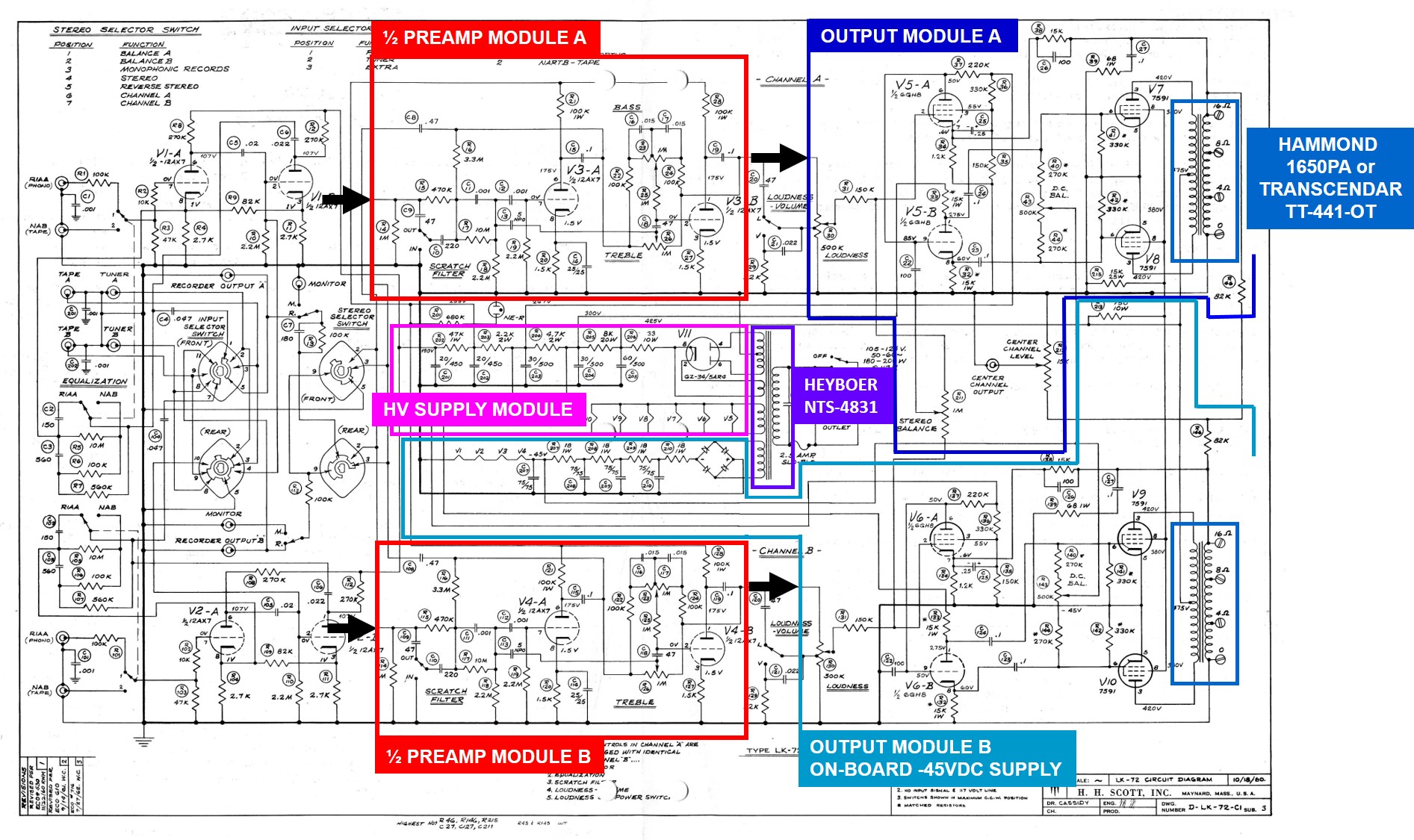
The approach used here partitions various sections of the amplifier into "modules" and individual hardware components as is shown in the figure below. The power supply transformer and two output transformers are off-the-shelf components purchased from sources listed above. There are four modules each completely contained on PC boards. The modules consist of the following: (1) a Preamp Module that has both CHA and CHB preamp circuits and independent Treble and Bass adjust, (2) a High Voltage Power Supply Module providing necessary DC voltages and heater power for the four 7591 output tubes and two 6GHB Phase Inverter tubes, (3) a CHB Power Output Module with on-board -45VDC supply for DC Balance and filament power for up to four 12AX7 tube heaters and (4) a CHA Power Output Module with Stereo Balance potentiometer. Center Channel output and output level adjust. The output of each channel is adjusted using a logarithmic taper input potentiometer located at the chassis input section. A detailed description of each module is provided below.
HIGH VOLTAGE POWER SUPPLY MODULE
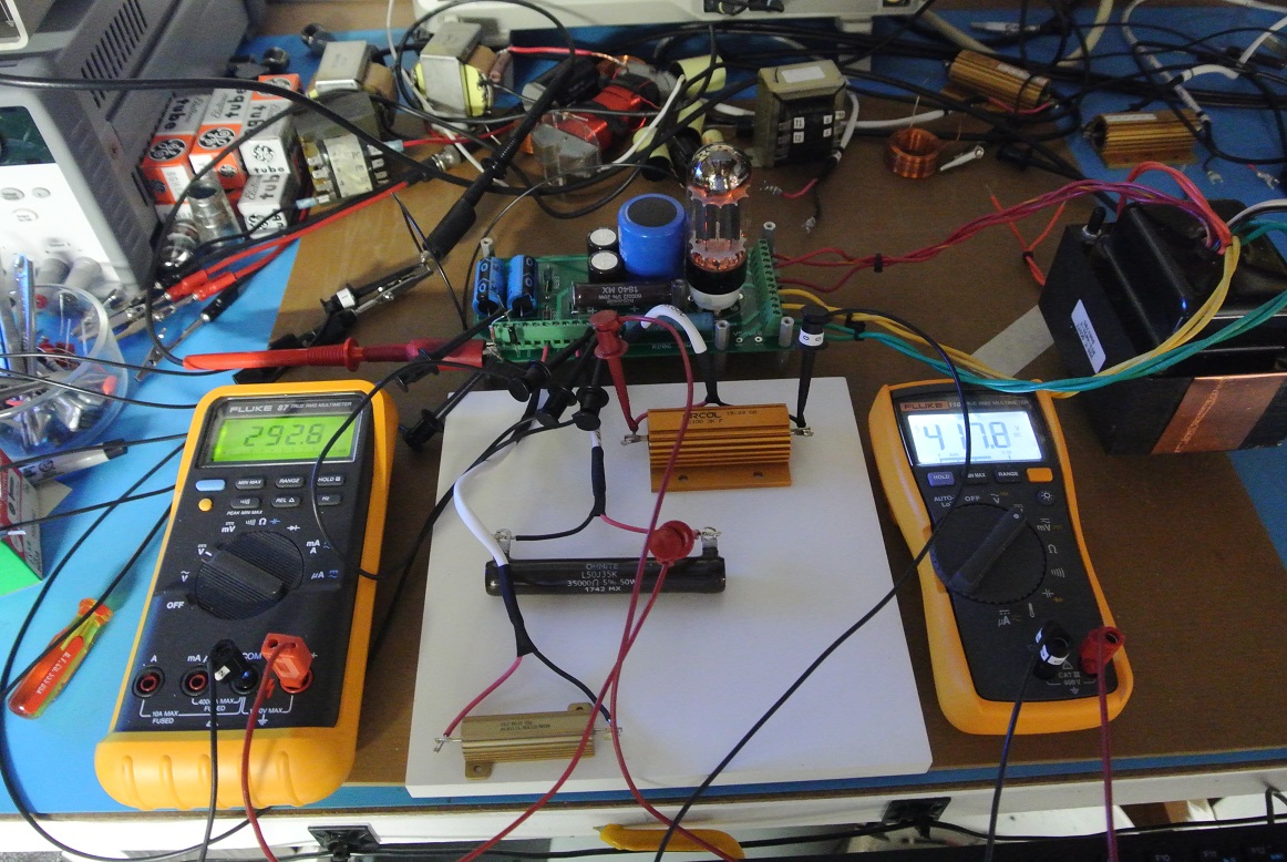
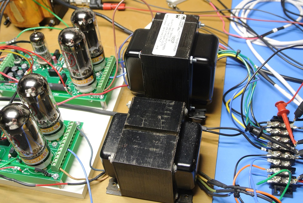
The High Voltage Power Supply Module provides high voltage rails to the preamp and amplifier power output modules. Based on the widely available 5AR4 rectifier tube the board sources 425, 300, 267, 255 and 190VDC supply rails and filament power to the 6GH8 phase inverter tubes, 7591 power output tubes and, if the preamplifier modules are used, plate voltages for up to four 12AX7 preamplifier tubes. Unlike the original power supply, the PC-board based module uses discrete capacitors and oversized power resistors, each rated for significantly highly loads than is required by the amplifier. Endurance tests using resistive loads (photo lower right) has demonstrated ample elevated temperature capability.
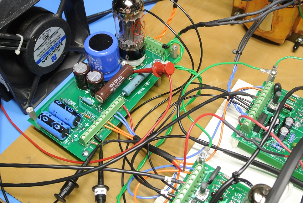
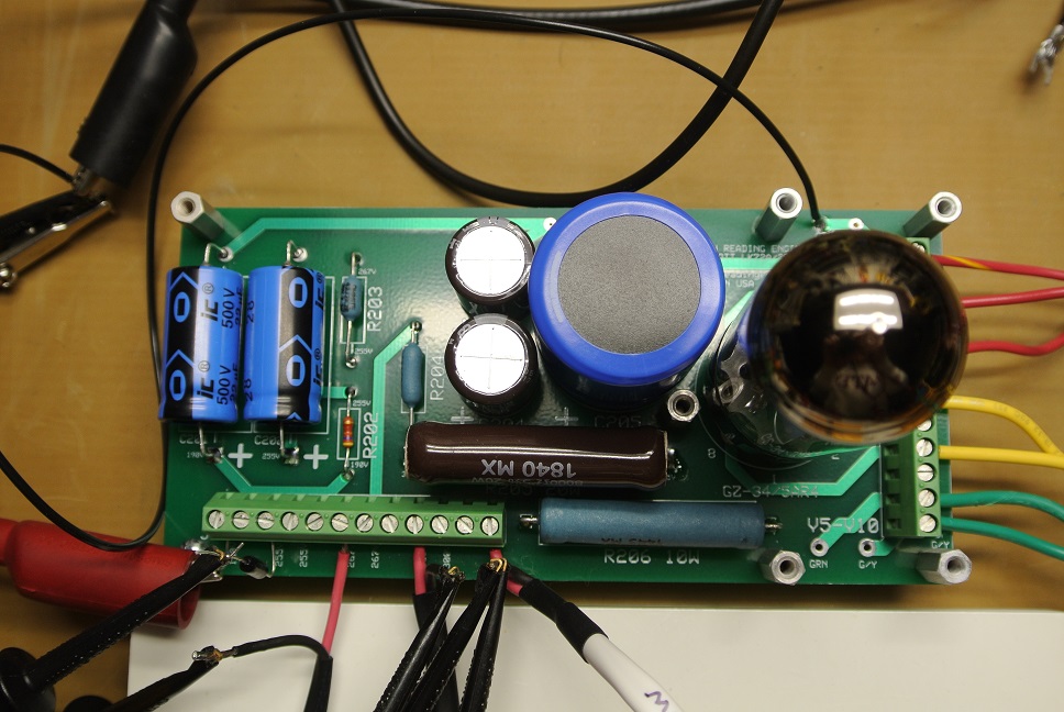
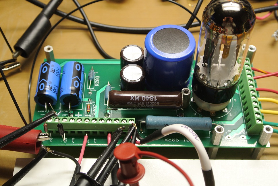
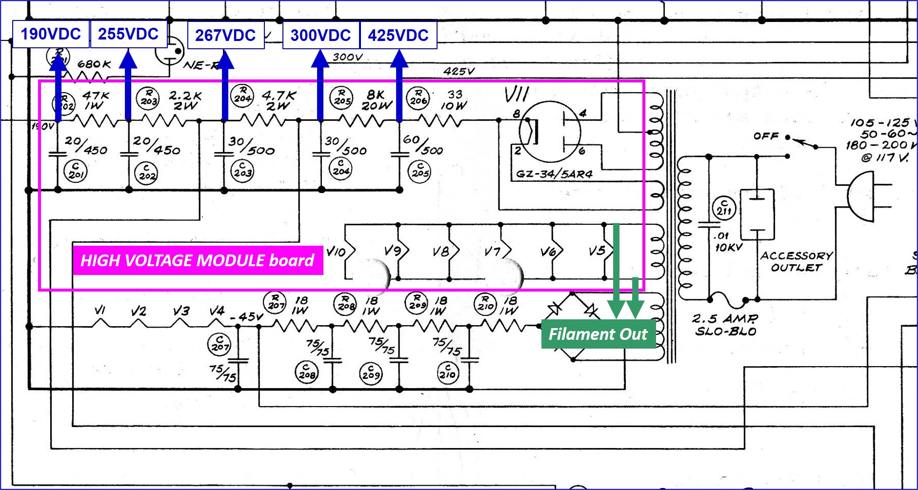
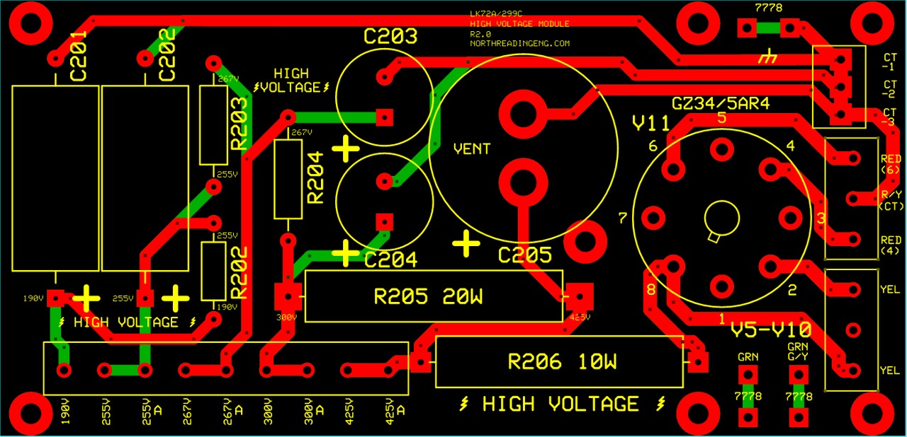
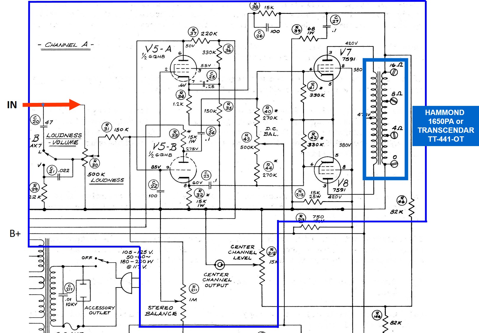
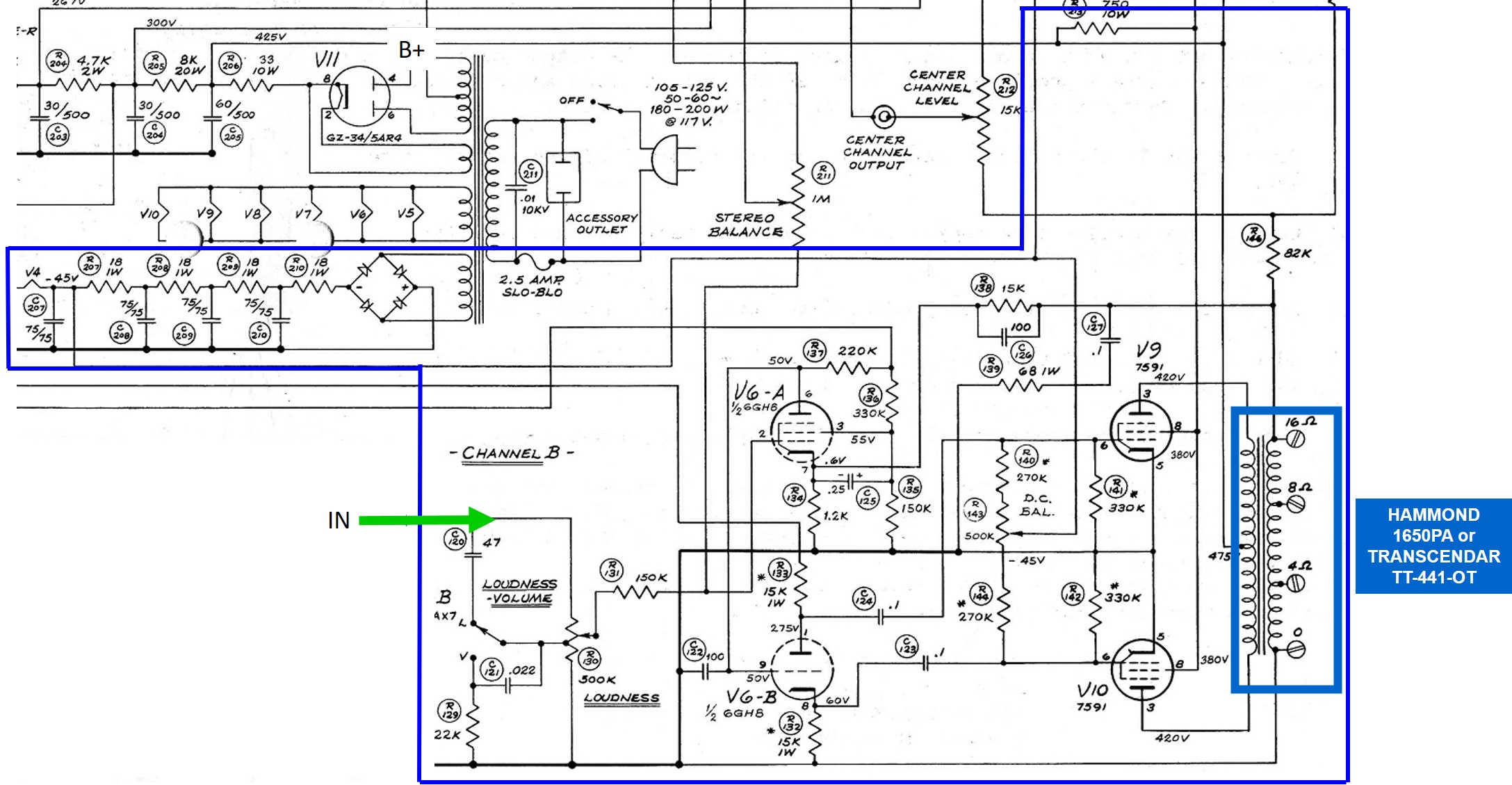
The factory schematic of the amplifier high voltage power supply is shown below, excised from the LK-72A schematic. The HV module board prototype, shown above, is derived from the circuit contained within the magenta border below. High voltage taps are identified by the blue arrows on the schematic. Board traces that tie back to the filament power supply section of the transformer secondary are terminated using Keystone PC board screw terminal posts capable of accepting 16AWG wire to provide filament current to the two 6GH8 phase inverter tubes and four 7591 power amplifier tubes (V5-V10). The leads are tapped off the board at the locations shown on the factory schematic by the green arrows. A three position center-tap terminal block is provided on the board which allows both the CHA and CHB center-tap drains to have a dedicated connection back to the center-tap of the power supply. The production version of the two layer PC board layout is shown below the schematic. Top layer traces are shown in red and bottom traces in green. Power supply transformer leads to the rectifier socket and leads back to the center-tap are dual traced. Lead wires are either 400 or 600VDC rated and terminated in ferrules. Terminal blocks are sourced from Phoenix. Photos of the final design iteration of the HV supply module are shown below the schematic. The Green/Yellow lead is the chassis ground that ties the three modules and small signal shield drains to the chassis at the power supply transformer. The connection to the Earth prong on the filtered, switch illuminated, 3FLA, AC Power Entry module is tied to this location.


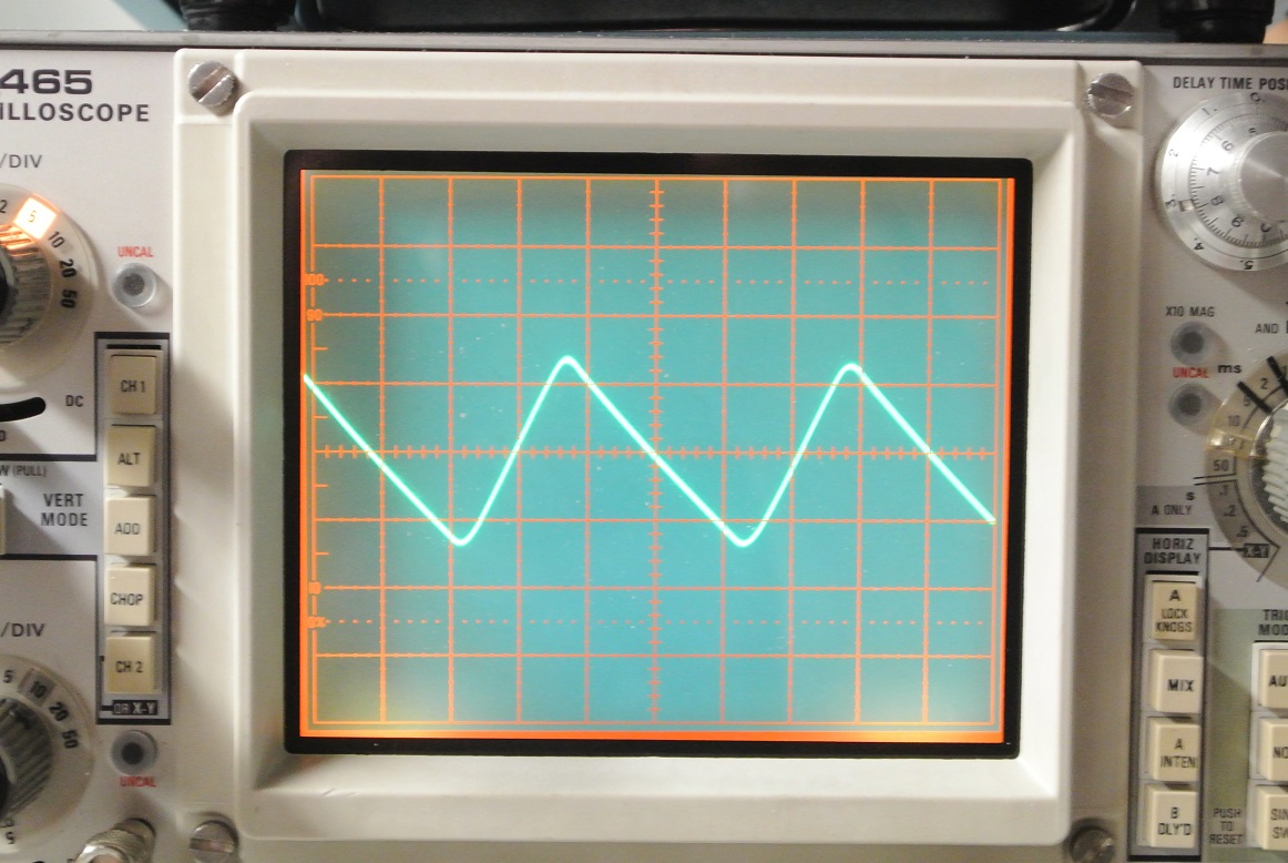
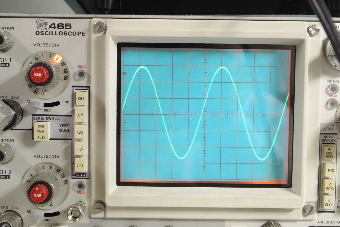
AC ripple voltage was measured using a HV scope probe sensing the 425VDC B+ supply tap and, by way of an autotransformer, the input power supply voltage to the power supply transformer primary set to 120VAC. As is shown lower left, the B+ supply evidences a 14Vp-p AC magnitude (scope at 5V/div) which is equal to about 4.9V RMS of ripple. With a 120VAC input voltage at the wall socket, the B+ rail will provide about 433VDC to the output transformer primary center-tap. The LK-72A is designed to operate between 105-125VAC wall voltage. All voltage magnitudes shown on the schematic are taken with the input voltage set at 117VAC.
The 300VDC supply ripple is shown, lower right. As is shown in the trace, the ripple magnitude is low (scope at 50mV/div). The 300VDC tap evidences about 60mVp-p ripple or about 22mVAC RMS.
CHA OUTPUT POWER MODULE
The CHA Output Power Module is shown below and consists of one 6GHB tube (V5) and a push-pull pair of 7591 Power Amplifier tubes (V7-V8). The DC Balance pot is located adjacent to the amplifier tubes. The output of the module is adjusted by a chassis mounted potentiometer. The Center Channel Output level adjust and Stereo Balance potentiometers are connected from this module and located on the chassis.

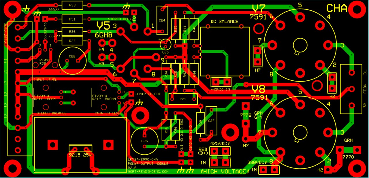
The CHA schematic is shown below. Components contained within the blue boarder (minus the output transformer) are located on the board. The switchable LOUDNESS contour option has been discarded and a potentiometer with logarithmic taper selected to adjust the level of the input signal to the module. Examining the factory schematic, capacitors C20 and C21 are disabled when the VOLUME position of the LOUDNESS-VOLUME switch is engaged, In this build, a logarithmic taper potentiometer was selected to approximate the attenuation produced by the R30 potentiometer in conjunction with R20.
CHB OUTPUT POWER MODULE
The CHB Output Power Module is shown below and, like the CHA module, consists of one 6GHB tube (V6) and a push-pull pair of 7591 Power Amplifier tubes (V9-V10). The DC Balance pot is located adjacent to the amplifier tubes. The -45VDC supply for DC Balance and up to four 12AX7 heaters is located on the lower left corner. The output of the module is adjusted by the potentiometer located extreme left, top.

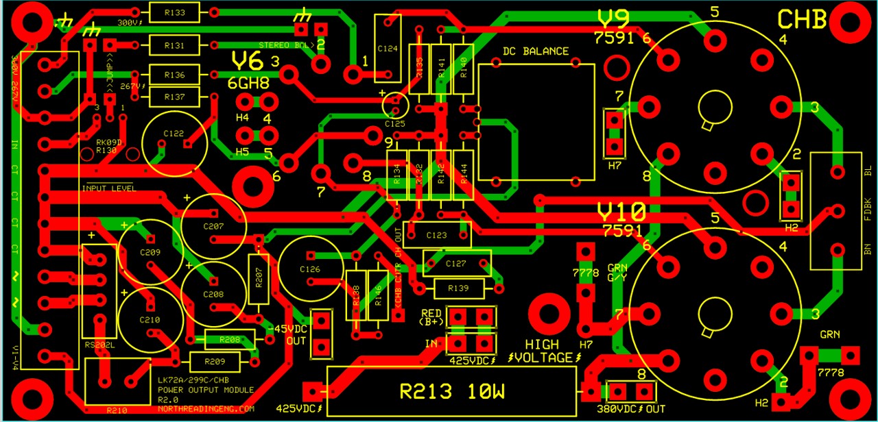
The CHB Output Power Module board shown above is derived from the circuit contained within the light blue border below. The -45VDC supply provides voltage to the CHA and CHB DC Balance pots and up to four 12AX7 heaters wired in series (V1-V4). When the amplifier is not used with the preamplifier boards a 340 Ohm power resistor is attached to the circuit to provide proper loading.
HIGN VOLTAGE WIRING
High voltage connections made between the HV Power Supply module and the two Power Output modules are shown below. Chassis GND connections tie back to the Earth prong on a standard NEMA 15A power plug. Wire to board connections on all the HV leads are facilitated using Faston 250 crimp terminals that are also soldered to the wire end and insulated in shrink tubing.

POTENTIOMETER PLACEMENT
Potentiometers can either be PC board mounted type or, as was done on this build, installed on the chassis plate (the power output boards will accommodate either configuration). There are four potentiometers installed on the chassis plate. A schematic and photo is shown below. In the photo, a green lead connected to each potentiometer ties the potentiometer 0V reference back to the PS transformer center-tap. Small-signal connections are made using single conductor, 24AWG, braided shield, "microphone" cable (Alpha wire 1703). On the board side, small-signal connections are soldered directly to the board. Adjacent to each small-signal connection is a solder pad to provide a return path to chassis ground enabling a convenient means of tying one end of the braid shield to the chassis ground.


AMPLIFIER FREQUENCY RESPONSE - TRANSCENDAR OUTPUT TRANSFORMERS
Frequency response between 50Hz and 80kHz of both channels is shown below using the Transcendar TT-441 output transformers. Test signals are cross-correlated MLS. CHA (top) and CHB (bottom) responses are shown. As shown in the plots the bandwidth in both channels is similar and about 3dB down to 40kHz. Output tubes are JJ Electronics, DC Balance adjusted prior to measurements. Input signal from analyzer source is 0.5VRMS, input level pots set to maximum, load across each transformer is a non-inductive 50W 8 Ohm power resistor. Capacitor C26 (CHA) and C126 (CHB) are 100uuF and responsible for feedback loop compensation and response behavior above 30kHz. MLCC type are required for these capacitors.
![]()
AMPLIFIER FREQUENCY RESPONSE - HAMMOND OUTPUT TRANSFORMERS
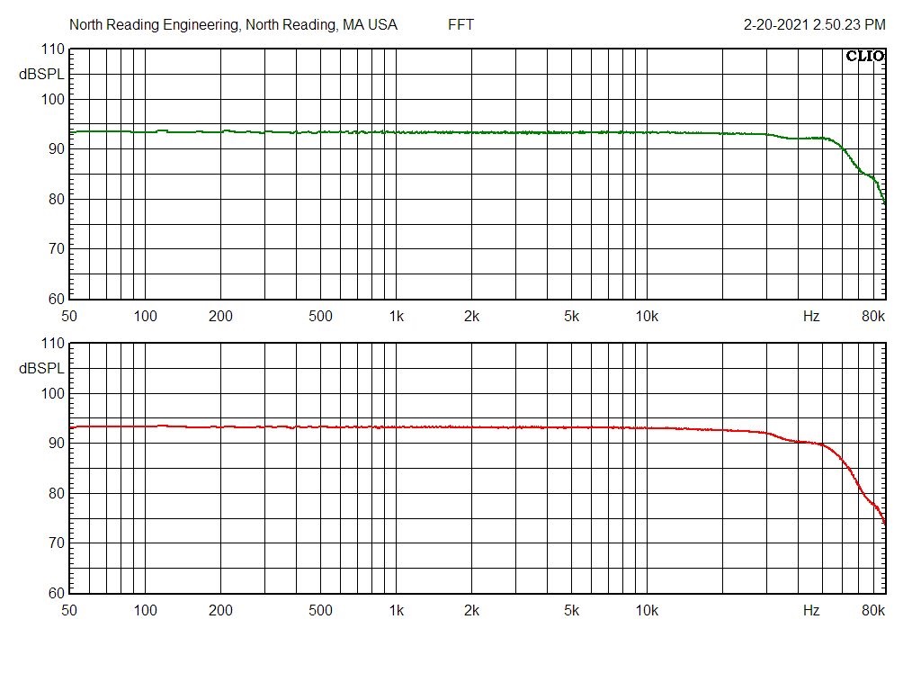
Frequency response between 50Hz and 80kHz of both channels is shown below using the Hammond 1680PA output transformers. Test conditions are the same as above. Capacitor C26 (CHA) and C126 (CHB) are required to be somewhat larger at 200uuF (MLCC type).
The bandwidth measurements, using either output transformer pair, are excellent.
AMPLIFIER % TOTAL HARMONIC DISTORTION 1kHz - TRANSCENDAR OUTPUT TRANSFORMERS
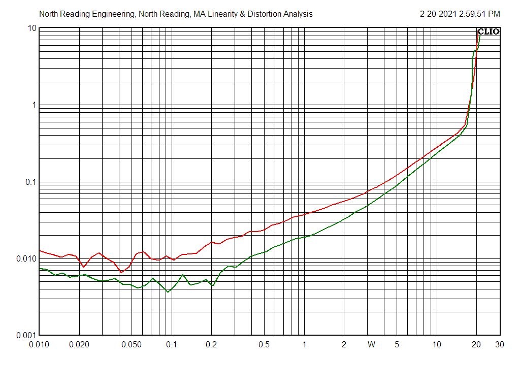
Amplifier %THD at 1kHz is measured across an 8 Ohm, non-inductive, power resistor over the entire power range of each channel and shown in the plot below. The response plots show typical increasing distortion as output power level increases. Maximum plate dissipation for the 7591 is 19W RMS. The LK-72A output power rating specified in the Scott assembly manual is 40W/channel which, presumably, is a "program" power rating. Program power (or "music" power) is approximately 2X the RMS power rating.
![]()
AMPLIFIER % TOTAL HARMONIC DISTORTION 1kHz - HAMMOND OUTPUT TRANSFORMERS
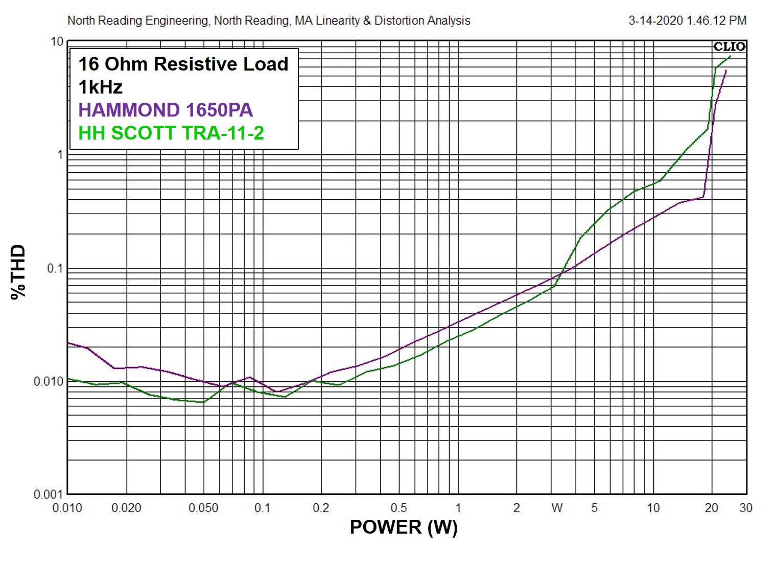
Comparing the Hammond response to the Transcendar response above shows a small improvement in total harmonic distortion measured at the lowest power output magnitudes when using the Hammond 1690PA output transformers.
A %THD comparison of the Hammond and LK-72A TRA-11-2 output transformers at 1kHz is shown in the plot below (right). The response plots show that the distortion behavior of the two are similar.
KROHN-HITE DISTORTION ANALYZER
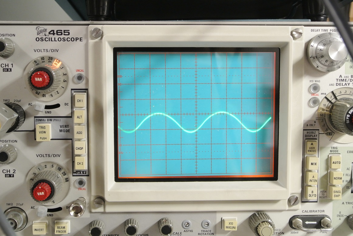
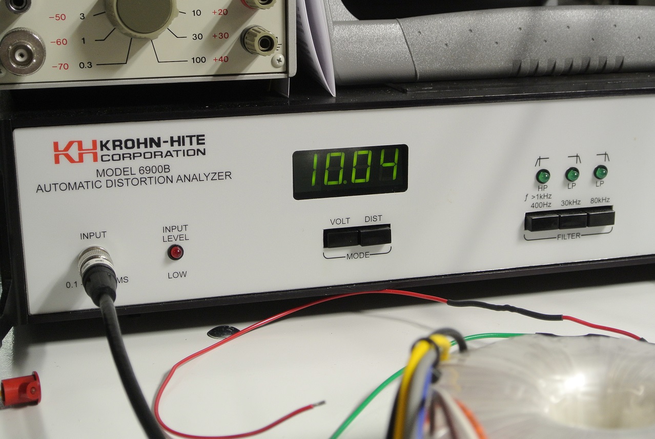
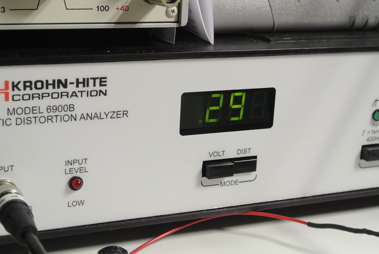
A Krohn-Hite 6900B Distortion Analyzer will source a 10V RMS sinusoidal signal (600 Ohm source impedance) with 0.002 %THD distortion to a device under test. The 6900B is able to analyze distortion components to 1MHz. The analyzer provides a distortion output signal which is the input signal after the fundamental is removed allowing for a detailed examination of the distortion components on the spectrum analyzer. Here, the test signal from the analyzer is used as an input to the CHA amplifier module working into the Hammond output transformer. Using the input level adjust pot on the module, the analyzer signal was trimmed for an amplifier output of approximately 10V RMS measured across an 8 Ohm, non-inductive power resistor load (~12.5W RMS output). Scope trace below is the signal across the resistor load (28.5Vp-p). A %THD of 0.29% was measured at this output voltage magnitude, consistent with the distortion levels measured on the CLIO analyzer.
AMPLIFIER CHASSIS PLATE AND ENCLOSURE
A chassis plate that provides mounting for the the various components of the amplifier is fabricated from 1/4" thick high strength Aluminum alloy plate. It is CNC machined, deburred and top surface brushed for an attractive appearance. The perforated steel enclosure housing the amplifier components is available from Hammond Manufacturing (PN: 1451-22). The enclosure is mounted to the chassis plate with four machine screws.
PREAMPLIFER MODULE
A two channel Preamplifier Module has been developed based on the LK-72A design using the 12AX7 preamplifier tube and will be described in a separate webpage.
AMPLIFIER MANUFACTURERS AND BUILDERS
Amplifier manufacturers interested in sourcing the assemblies shown above from North Reading Engineering may inquiry at audio@northreadingeng.com. North Reading Engineering has the capability to provide fully assembled and tested modules for integration into your chassis configuration. Those interested in obtaining assembled modules, chassis plates, partial or fully assembled amplifiers are requested to inquire at the email address above.
AMPLIFIER ASSEMBLY PHOTO GALLERY


This webpage and its contents are the property of John Warren of North Reading Engineering, North Reading, MA 01864 USA. No part of the above work may be copied and published, in part or in total, without permission.
� 2021 John Warren