MOD THE CROWN D45-75A SERIES AMPLIFIERS INTO THE IDEAL, ACTIVELY FILTERED, AUDIO POWER AMPLIFIERS


INTRODUCTION
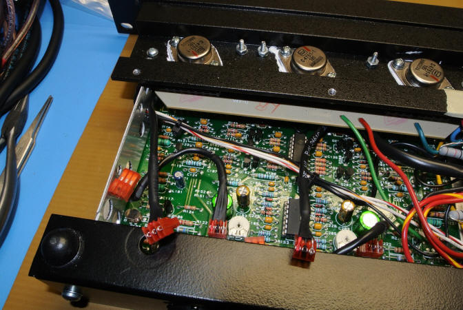
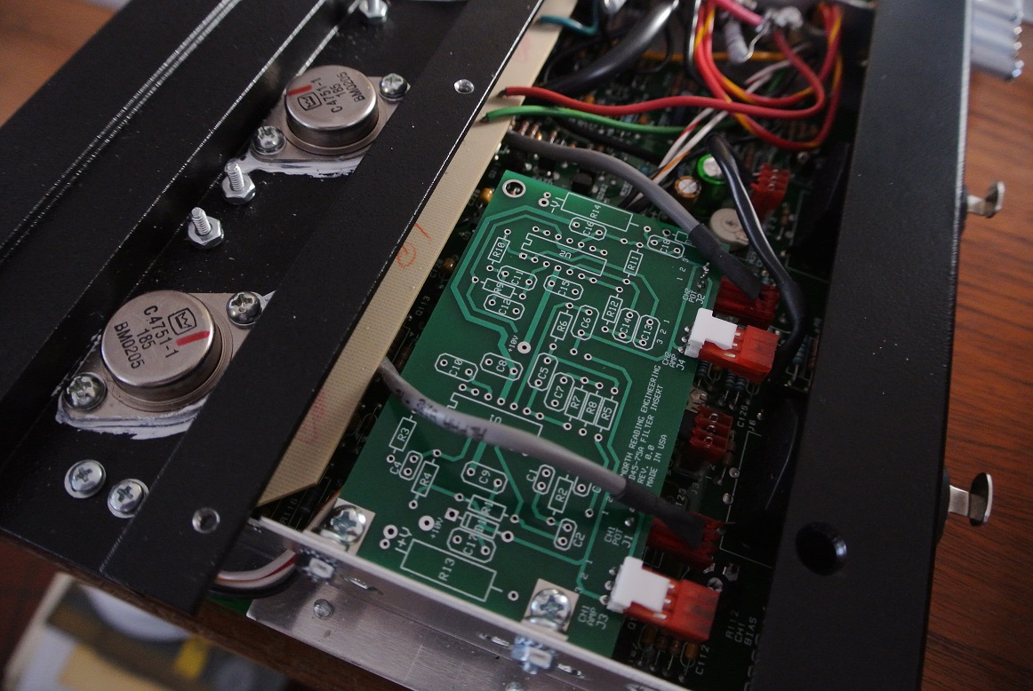
This page describes an active filter that, when installed in the Crown D45-75A series of amplifiers, converts CHANNEL 1 of the amplifier to a (steep slope) 24dB/octave band-pass filter and CHANNEL 2 to a 24dB/octave high-pass amplifier. The filters are cascaded Sallen-Key architectures and utilize two Analog Devices AD713 quad packages. The PC board is about the size of a credit card and uses the existing MTA-100 Series pin connectors in the amplifier to make the necessary connections. Some soldering is required but for most DIY types, it's easy. The modified amplifier is ideal for actively filtering and amplifying midrange and tweeter signals in three-way horn and direct radiator loudspeaker systems. The Sallen-Key architecture is well documented and the filter can be tailored, within the constraints of the filter topology, to the crossover frequencies required by the user. The filter can also be configured as a Linkwitz-Riley linear phase crossover for two way systems where CHANNEL 1 is dedicated to the woofer and CHANNEL 2 to the high frequency driver. The output of each driver is set by the gain potentiometers dedicated to each channel. Thus, while in use, the output of either the midrange or tweeter drivers can be adjusted independently.
SYSTEM CONFIGURATIONS
Three-way, L&R Channel System #1
A three-way system consists of a woofer, midrange and tweeter. The modified amps are capable of providing independently filtered and amplified signals to the midrange and tweeter drivers in any three way loudspeaker that allows access to the individual driver terminals and examples include the Klipsch Klipschorn, Belle, and LaScala. Presuming the user has a stereophonic, two-channel system, two modified Crown amplifiers are required, one for left and one for the right loudspeaker. Bass frequencies are then handled by a separate two channel amplifier which can be either passively or actively filtered. The bass amplifier is selected to provide the best match to the low frequency unit with respect to power and load impedance.
Three-way, L&R Channel System #2
In this configuration, three modified Crown amps would be used, two dedicated to handling mid and high frequency drivers as described above and a third providing actively filtered low frequency signals from CHANNEL 1 to the left woofer and from CHANNEL 2 to the right woofer. Thus, all drivers are actively filtered and their outputs set independently using a stacked amplifier arrangement consisting of three Crown amps. The bass filter would be a 24dB/octave band-pass with -3dB corner frequencies selected to accommodate the woofer operating range.
Two-way, L&R Channel System #3
A two-way system comprises a woofer and tweeter. In this configuration, two modified Crown amps are used. Here however, the -3dB low end corner frequency of the band-pass filter (CHANNEL 1) is set to accommodate the low frequency limit of the woofer, the crossover frequency to the tweeter is then selected as required. For designs where the acoustic centers of the low and high frequency drivers are co-planer, the C and R values of the filter can be chosen to provide a Linkwitz-Riley, linear phase in the electric domain of the crossover.
SELECTING CROSSOVER VALUES
For builders that wish to develop their own filter configurations, a pair of PC boards and necessary small signal cables, headers and mounting hardware for the D45-75A amps can be purchased as a kit. The builder would then solder all components in place (schematic provided) and chosen R and C values to suit their particular application. North Reading Engineering will also provide any assistance needed to select component values and model the response for any system requirement.
To illustrate the flexibility in the Sallen-Key architecture, the capacitor values C1, C2, C3 and C4 shown below (where C1=C2=C3=C4) and stepped from 50nF to 1920nF in increments of 80nF. The SPICE simulation at right shows how the high-pass section of the band-pass filter is changed.


And by changing R5, R6, R7 and R8 (where R5=R6=R7=R8), the low pass section of the midrange filter can be altered as shown below by the simulation. The dark blue curve is the simulated tweeter response. The hot pink curves show how reducing the resistor values from 2.37k to 1.18k in increments of 197 Ohms increases the low pass section of the midrange band-pass filter. Reducing the values of the resistors increase the crossover point given the fixed tweeter response.

MEASUREMENTS
Frequency Response
For measurements both CH1 and CH2 have an 8 Ohm power resistor as a load. The FFT analyzer is a CLIO FW with input signal cross-correlated with the output. The analyzer senses the signal across the load resistors. On the midrange band-pass graph shown below (left) the green plot is the response with the front panel gain set full. By turning the pot down 2 "clicks" for each FFT sweep the output level is lowered and the magnitudes are shown in the graph. The graph at right is the tweeter high-pass response and a single click of the pot is shown for each sweep. The relative output between the two drivers can be adjusted to greater differences than what's being shown here. For example, the user can shut the tweeter off and drive the midrange to maximum output if so inclined. The ability to individually tailor the gain of the drivers while critically listening to the system provides for a degree of flexibility that's not possible using passive networks. Also, to realize the steep slopes developed by the cascaded Sallen-Key architecture, a passive filter network configuration would require a "wheelbarrow" of capacitors, inductors, resistors and autotransformers.


Distortion
%THD of both the band-pass midrange (CH1) and high-pass tweeter channels of the amplifier were measured using a 196kHz sampling frequency to the maximum voltage output of the amplifier. The load on both channels is an 8 Ohm load resistor. The graph below show the %THD of the tweeter channel (blue) using a 20kHz input. As is evident in the plot, distortion is no more than 0.10% dropping to nearly 0.02% near full power output.
The green and red plots are the %THD of the band-pass midrange at 500 and 1000Hz, respectively. The abrupt steps in the band-pass plots are associated with the design of the amplifier. When the current draw from the amplifier is significant, the output stage transistors take over from the driver transistors and deliver the necessary current. From the two plots, the transition at 500Hz is a bit lower in output voltage than at 1000Hz. Note also, the midrange signal must pass through two cascaded Sallen-Key filter architectures which will contribute to %THD. That said, maximum %THD is still quite respectable at about 0.10% max. at 500Hz thanks to the very low %THD of the AD713.

HARDWARE PURCHASE OPTIONS
Finished Filter Boards, User Install: Pair of finished filter boards, op-amp rail voltage leads soldered in place, (2x) amplifier-to-filter cables, (2x) filter-to-potentiometer cables, mounting hardware including fasteners, brackets and stand-offs. Built with C and R values to accommodate user defined crossover frequencies. - $179 (some soldering required, board level test results provided, two amplifiers required)


DIY Filter Boards: Pair of PC boards (unpopulated), (2x) 14 DIP sockets, (4x) 3-pin MTA headers and op-amp rail voltage leads soldered in place, (2x) amplifier-to-filter cables, (2x) filter-to-potentiometer cables, mounting hardware including fasteners, brackets and stand-offs. - $79. (PC board level soldering required, schematic and parts list provided, temperature controlled soldering station required, ESD precautions, testing prior to install recommended)
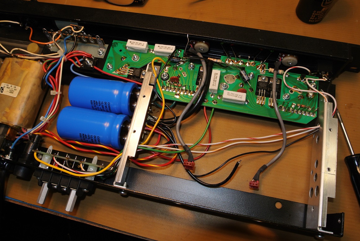
D45-75A Reworks, Vintage Crown Amplifier Repairs and Restorations: Power supply reworks, recaps, repairs, rebuilds including chassis hardware replacement (contact North Reading Engineering).

Website and contents property of North Reading Engineering, North Reading, MA 01864 USA. No part of the above may be copied and published, in part or in total, without permission. © 2017 John Warren